


Famous lines indeed, from "The Sound of Music" ... but for Makers dabbling in Arduinos and Raspberry Pis, programming and electronics, it might as well be:

Blinking an LED, often the quickest way to get up and running, and gets you a satisfying result you can actually see!
"Look Ma, I can make that LED blink, just by a few lines of code!"
When using an LED, you are often warned to use a resistor with it. If you haven't been warned yet, here goes - you NEED to use a resistor with it!
What is the value of the resistor to use? Why is the resistor needed? If you're new to Making and Hobby Electronics, the heuristic answer often seems to be 220 ohms! 😊 This is a good value of resistor to use with an LED on Arduino.

The short answer to the question is this - the resistor helps to limit the current through the LED to an acceptable value! The value of the resistor (measured in Ohms) should be such that the current is at the value we desire (measured in Amps, or milli amperes or 1/1000 of an amp). Now what is this value and how is it important?
Let's start at the very beginning ... a very good place to start!
Ok, no more "The Sound of Music" references, I promise! (at least until the next one!) 😊
Let's start with a simple circuit we use for a Blink Arduino Sketch – we have an LED, connected to the Arduino as shown (we've picked pin 10 in our example), with a resistor placed in between.

We use digitalWrite(10, LOW) and digitalWrite(10, HIGH) to turn off/on the digital pin 10 respectively. Our GPIO pin acts like a battery that we can turn on and off, using code!
This is the equivalent circuit:

The GPIO pin acts like the battery to power the LED, and you can turn on/off this battery using code. You see, the wee little battery of the GPIO pin of the Arduino cannot supply too much current. Each LED also has a maximum current that it can tolerate.
Datasheets/Tech Specs give you ... Data!
First thing to note is that plenty of information is available – the trick is to know where to look. Here, the main advice I can give you from my own meandering experience is ... datasheets and tech specs.
Datasheets and Tech Specs give you invaluable information about a particular component or board. We'll see that these will be very useful in our journey to figure out the answer to the question - What is the value of the Resistor? We'll need information from both Arduino and from the LED we are using.
Let's first start with the Arduino. If you get to the Arduino Uno product page (https://store.arduino.cc/usa/arduino-uno-rev3), it has a tab called "Tech Specs". I've attached a screenshot of it for your convenience with the data of interest highlighted:

It has a lot of information. We are interested currently in two bits of information. It operates at 5 Volts(V), and each I/O pin of the Arduino Uno can supply 20 Milliamperes (mA).
Now let's shift focus to the LED. Here, I've taken the "Diffused Red 5mm LED (25 pack)" from Adafruit, as an example. Adafruit (and Sparkfun too) is pretty good about providing Datasheets for most of the products they sell. If you navigate to the link that says "Datasheet" in the link above, you can open up the PDF document.
There's plenty of information there, so the trick is to know what you're looking for (and in the long run, also take the time to read through the other stuff there and start to understand it). I've attached a screenshot with the relevant sections of the LED's Datasheet highlighted, for your convenience:
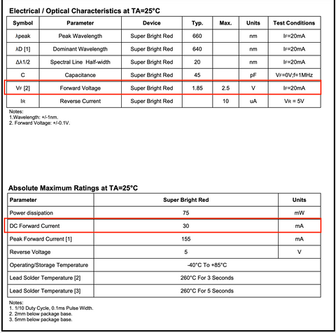
We see that this LED can take a maximum current of 30 mA. Our Arduino I/O pin can only supply 20 mA at most, so that is the gating current value. We also note that the forward voltage of this LED is about 1.85V (the Typ. or Typical value).
Also note that sometimes, the seller does not provide the full datasheet, but rather just the important values. For example, Adafruit does not provide a datasheet for their "Diffused Red 3mm LED (25 pack)" product, but it does provide the important values in the product page, as shown below:

Here, we see that the forward voltage of their 3mm Red LEDs is about 1.9-2.3V. We can take an average value of 2.1V.
The forward voltage represents the Voltage drop across the LED in order to have current flow over it and provide light. If you supply a voltage less than this, the LED will not light up.
Ohm's Law
The first and most important law you will come across in electrical circuits is Ohm's law, that states the relationship between current, voltage, and resistance. It was discovered by Georg Simon Ohm and published in his 1827 paper, The Galvanic Circuit Investigated Mathematically.

It states that the amount of steady state current (I) across a conductor is directly proportional to the voltage (V) (also known as potential difference) across it.
Therefore, if the voltage (V) across such a conductor triples, the current (I) across it also triples, and the quotient V/I remains a constant. This quotient is called the resistance of the material (R), and is measured in Ohms. The current is measured in units called Amperes (A) and the voltage is measured in Volts.
In other words, R = V/I
It can also be rearranged to write as follows:
V = IR ..... equation 1
I = V/R
Such materials that follow Ohm's law are called ohmic, and a vast majority of materials we'll face in getting started with Hobby Electronics fall under this category, so this is an important relationship to understand.
Voltage, Current and Resistance for a circuit in Series
Our Arduino circuit is an example of a series circuit. A series circuit is one where there is only one path for the current to flow. Here is an example:

The same current I flows through the entire circuit as there is only one path for the flow of current.
The resistance of components in series adds up for the circuit. The total resistance R of the circuit is thus the sum of R1, R2 and R3.
R = R1 + R2 + R3 ...... equation 2
The voltage drops across individual components (V1, V2 and V3) also add up. The total voltage drop across the circuit V is thus the sum of V1, V2 and V3:
V = V1 + V2 + V3 ...... equation 3
This might seem like a lot of information, and it is! But this is quite useful in understanding the relation between the LED and the resistor, and how much should the resistor's value be, so please bear with me for a bit! 😊
Putting it all together
Let's go back to our Arduino Blink circuit schematic, and this time, let's plug in some numbers we already found out from our Datasheets/Tech Specs. Our Arduino provides an operating voltage of 5v, so the "battery" provides 5V. Our LED (let's use the Red 5mm LED from Adafruit as an example) has a typical forward voltage of 1.85V, so the voltage drop across the LED is 1.85V.
We know that the current is the same across the entire circuit, and we know that the maximum current the Arduino I/O pins can provide is 20 mA. We therefore want to choose some value we would like that is <= 20 mA.

We can choose the maximum value of 20 mA. But that also means we'll be consuming more power. If we're powering the Arduino by a 9V battery, for example, we can get more life out of the battery by minimizing our current usage.
Here again, the datasheet is your friend. In our example with Adafruit's 5mm Red LED's datasheet, it also provides information on relative luminous intensity as compared to the current:

We can see that picking 10 mA is going to cut the luminous intensity by about half. You can check to see if this level of brightness is something that works for you.
For example, if you're going to be using your Arduino Blinker indoors and in low light conditions, you don't need it to be super bright. If you're using it outdoors or along with other light sources, you may want to turn up the luminosity.
Let's pick 10mA as our target current as a reasonable compromise - you may be able to get a brightness level that works for you with even a smaller current.
From Equation 3 above, we know that
V = V1 + Vf
We also know V = 5V (the operating voltage of the Arduino and the , and Vf = 1.85V
Therefore, the voltage drop across the resistor will be
V1 = 5V - 1.85V = 3.15V
We also know from Ohm's law that
V1 = I * R1 where I is the current we want to consume (10 mA).
Therefore,
R1 = V1/I => 3.15V / 10mA = 3.15V / 0.01A = 315 Ohms (I = 10 mA)
Now, if we want to get maximum brightness from our LED, we'll want the Current I to be 20mA. In that case, our new R1 will be
R1 = V1/I => 3.15V / 20 mA = 3.15V / 0.02A = 157.5 Ohms (I = 20 mA)
There are some practical considerations for the value of the resistor we can use. Resistors are manufactured in some discrete values, so we are bound by what value resistor we can get.
The following provides a list of standard resistor values available (https://ecee.colorado.edu/~mcclurel/resistorsandcaps.pdf), shown here for convenience. I've highlighted the closest values to our 157.5 Ohms and 315 Ohms (rounded up).

Thus, we'll pick 330 Ohms (or 160 Ohms if we want it brighter). Now, we can go back and calculate the exact current we'll be consuming!
I = V1/R1 => 3.15V / 330 Ohms = 0.00954 Amperes = 9.54 mA
In our second case,
I = V1/R1 => 3.15V / 160 Ohms = 0.0196875 Amperes = 19.69 mA
By rounding up the resistor value rather than choosing a lower number, we ensure that we stay below our maximum limit of 20 mA!
Now we can blink away to glory, can we not? 😊 And while we're at it, we can do so safely without damaging either the Arduino or the LED!
I hope you have found this helpful! There are many online LED Resistor calculators available where you can plug in the values and it will give you the resistor required - but you see that the math involved is minimal and you can now do it yourself. Or if you do use the online tools, you'll know how they work, and you also know now where to get the information to plug in. More importantly however, you know how to use LEDs together with their associated resistors to keep everything safe AND bright!
If you liked this, then I think you will like the project "Traffic Light Redux! -Intersection with Walk Request Buttons"! It has 10 LEDs and 2 buttons simulating a Traffic Intersection with Pedestrian Walkways and Walk Request buttons! Using our ProtoStax Enclosures, you can make a nice compact prototype that would function as a great show-and-tell while protecting your Arduino and wiring. It also has some neat programming tips and tricks to learn from – State Machines and bitmaps – if desired. We have a blog post about it that talks about it at a high level, and the Project Hub page, that has additional details including the code and full instructions.

Happy Making! 😊
Sridhar Rajagopal